It’s Halloween here at Hawk Ridge Systems, and we take the holiday dead serious. To spook my fellow co-workers, I decided to undertake a project I’ve been mulling over since I read an article about one last Halloween; the Aztec Death Whistle.
The Aztec Death Whistle, rather than being a cursed object, is really just a cleverly shaped whistle that mimics the sound of the agonizing screams and wails of captives being tortured. Neat!
Since I didn’t have the genuine article to study (might need to buy one when I go down to Mexico in April!) I had to use the interweb. I was able to gather these cutaway views from various articles and google searches, with no real guarantee any of these are based on authentic Aztec Death Whistles and not themselves just approximate recreations. With this understanding, I knew I might have to take a few attempts to perfect the air pathways and resonating chamber to get the terrifying effect I’m after.
Next, I broke open SOLIDWORKS and set about making my prototype of the whistle air chambers. Since I didn’t have the time to make a skull and everything from scratch, I was already planning to use an STL or mesh body and carve away the internal chambers; so instead of creating a negative of the internal passageways, I went with a positive I could use as a subtraction tool later.
This involved making a very simple right-hand sketch of the path of the air passages first and then using the new Circular Profile options in the Sweep tool to get the areas where air would flow in and out.
Doing it this way also means I can come back and adjust the internal cavity shapes later to my heart’s content, and either update the whistle with the new internal geometry or create an entirely different whistle using the same internal geometry and a different body/exterior. This is important at this stage because I’m not 100% positive the geometry I have will even work, so I need to be able to quickly revise and update it later. The resonating chamber was added next, as a simple half circle Revolves and merge feature.
With the body of my whistles’ internal cavities finished, next, I turned my attention to the final whistle itself. As I mentioned earlier, I didn’t have the time to make a good quality skull model using surfacing tools and my (lack of) artistic ability meant I was going to do what every good engineer does; look for an off the shelf solution. Why reinvent the skull when others have for you? I went to Thingiverse and got this fantastic skull STL that was already watertight as a cohesive single body. This is a kind of important factor since I didn’t want to spend any time at all really cleaning up this skull model before adding my own geometry and printing a prototype. I want to try my whistle dang it! Credit to YahooJapan for the STL.
“But wait!” you say, knowing SOLIDWORKS doesn’t always play nice with STL files, “How are you going to use that geometry?”
Convert to Mesh Body baby.
Introduced in SOLIDWORKS 2018, Convert to Mesh Body has been one of my favorite hack and slash tools, making quick work of otherwise scary jobs. In this case, the thought of recreating this skull or making one from scratch or bringing in this STL and trying to convert facets into surfaces and knitting into a cohesive face/body is downright terrifying.
So instead, I opened the Skull STL, inserted my whistle body as a part, and converted both to mesh bodies. This allowed me to play with both sets of geometry using SOLIDWORKS tools and combine them together. I positioned the internal whistle cavity body where I wanted inside the Skull STL, and then I used the Combine tool to subtract away the areas of the Skull where air would flow. To cap it off, I created a mouthpiece using native SOLIDWORKS geometry, converted it to a Mesh Body, and then also Combined it with the rest of the shape. Now I had a full Aztec Death Whistle Prototype, and I could move on to 3D printing one for testing and refinement.
Finally, I exported this finished Mesh Body as an STL again, so I could load it into my slicer software for 3D printing. As of this writing, I am waiting for my prototype to leave the printer! Stay tuned for a future article where we simulate, test, and refine this Whistle using SOLIDWORKS Flow Simulation tools.
Idaho Bureau Chooses HP Jet Fusion 4200 3D Printer to Enhance its Offerings
Jawstec started with a simple goal in mind; to create a simple process where you can get production ready parts for a fraction of the cost. They offer a unique depth of custom manufacturing and 3D printing services to a variety of industries including Automotive, Consumer Products, and Aerospace for both small or large businesses.
With the growing demand for Unmanned Aerial Vehicles (UAV) in recent years, Jawstec took it upon themselves to design an optimized drone. Unlike radio-controlled planes and helicopters, the product development varies in time and costs. Jawstec designed an enhanced drone with 3D Printing to make its parts stronger and lighter. The Jawstec team took it to open themselves to create a design that was more durable for the vast environment the drone would take flight in. They utilized HP Multi Jet Fusion 4200 3D Printer and Nylon PA 12 plastic materials for the parts. Their total design time took 18 hours with SOLIDWORKS and the total print time was 4 hours.The engineers’ focus was to design a drone that was stronger and lighter, and with the HP 4200 3D Printer it weighed 200 grams lighter than the original drone design and increased its total flight time to 28 minutes. Jawstec’s design team was able to print up to 10x faster and reduced their product development costs by half. This wouldn’t have been possible without HP robust and accurate multi-jet fusion technology. (more…)
Utilizing SOLIDWORKS Reference Geometry for Complex Designs
For basic SOLIDWORKS models, users can often complete designs by leveraging only the default planes and available model geometry. However, as the complexity of designs increases, it often becomes necessary to create and utilize reference geometry to produce models with appropriate design intent. Reference geometry includes planes, axes, coordinate systems, reference points, the center of mass, and mate preferences. In this article, we’ll cover the basics of creating planes, axes, and coordinate systems to help you throughout your design process.
Fly Reel Design
In this example, a fly reel is being designed, and so far everything has been smooth sailing.
At this point, we want to create a rectangular cut on one of the larger cylindrical surfaces of the fly reel, but there is no flat surface to create a sketch. While offset options in the Extruded Cut command could be used to accomplish this, creating a plane tangent to the surface will be more robust, and will result in better design intent should the design be resized in the future.
Features Tab
All types of reference geometry are considered features and can be found in the Features tab. To begin creating a plane, access the Features tab of the CommandManager, select Reference Geometry, and then click Plane.
In Part I of this series, we looked at how the smoothness of curves can be analyzed and controlled. Now we’ll be taking a look at some additional analyses tools to further evaluate our surfaces as well as ways to improve our curvature continuous connections.
The zebra stripestool (view>display>zebra stripes) allows us to see small changes on a surface that may be hard to see with a standard display. This tool mimics the reflection of long stripes of light on a very shiny surface. With zebra stripes, we can verify that two adjacent faces are in contact, are tangent, or have continuous curvature. As can be seen in the image below, the zebra stripes for contact do not have the same direction or size. The zebra stripes for tangent have the same direction, but change sizes where the tangency occurs – there are two points of tangency. And the curvature continuous stripes share the same direction and the same size throughout the entire surface.
Every year, Hawk Ridge Systems offers live Launch events for its customers to introduce the new enhancements of that year’s release. What if you were unable to make one of the 2018 live sessions? Don’t worry – we have you covered! We recorded the live stream (HawkLive 2018) of our first Launch event and separated it into 8 modules so you can easily digest what’s new in SOLIDWORKS 2018! Even if you’ve attended a launch in another city (besides San Jose, where this one was recorded), it’ll be different and exciting content! In today’s blog article, we’ll introduce some of the main topics we covered in Module 1, which includes a brief introduction to Hawk Ridge Systems, what to expect from the upcoming modules, and SOLIDWORKS customer’s we’re using to demonstrate the new enhancements of SOLIDWORKS 2018.
Introduction to Hawk Ridge Systems
Before we dive into the content, did you know that Hawk Ridge System offers:
All products that are currently developed by SOLIDWORKS and Dassault Systemes
A full range of 3D Printers and Scanners from HP, MarkForged, and Artec
SIMULIA Abaqus as our high-level analysis software
SOLIDWORKS CAM post processors
CAD, Technical Communications, Analysis Consulting, and Mentoring Services
Classroom, Online, and On-Demand Training Offerings
Custom written software like XBOM and PDMTeamWorksPro
Live Support chat (in addition to phone, email, and web)
Comprehensive Support documentation
Active and ever-growing YouTube channel, blog (like this one!), weekly webinars, and much more
What’s New in SOLIDWORKS 2018
Nearly half of the development projects SOLIDWORKS undertakes are based on quality and performance, which means, speeding up tasks, stability improvements, and bug fixes. The other half is the new features and enhancements that will be introduced in this blog and video series! There are over 230 pages (239 pages, to be exact) in the What’s New 2018 PDF, alone. It’d be nearly impossible to cover every single enhancement, but our team hand-picked some of the best ones they believe could benefit SOLIDWORKS users the most. Here’s a run-down of the 8 videos and what they’ll be covering:
There are numerous benefits for creating your part design as a multibody part ranging from performance to file management in SOLIDWORKS. However if you have tried to apply a material to a multibody part you will notice that the materials folder of the feature manger will apply the same material to every single body in your design. This works fine if you have a weldment structure which is all made out of steel, but most designs use a combination of materials to accomplish their design goals. In this example for a conveyor belt, there could be aluminum, steel and even rubber. One material could be applied to the entire design, however our mass property and simulation results would be inaccurate. (more…)
Using the standard SOLIDWORKS tools and features from the CommandManager is already an extremely efficient method to quickly bring concepts into a three dimensional model. However, many users prefer to leverage a variety of both standard and custom shortcuts through hotkeys or context menus for an even faster workflow. This article covers many of the most impactful default keyboard shortcuts in SOLIDWORKS, and describes how to customize them for maximum time savings.
While using SOLIDWORKS, all of the standard Microsoft keyboard shortcuts are available. As expected, CTRL-O can be used to open a document, CTRL-S will save the current document, and CTRL-Z will undo the most recent action. However, many additional SOLIDWORKS-specific keyboard shortcuts exist that can make potentially tedious point-and-click commands obsolete.
A few of the more popular shortcuts include using the spacebar to bring up the Orientation menu, which provides access to many standard views, as well as any custom views that have been saved. Pressing the R key will display a list of recent documents, and specific documents can even be pinned to the list permanently. Another great shortcut is CTRL-B, which will automatically rebuild your model. A table of some of the most popular default SOLIDWORKS keyboard shortcuts has been provided below:
One exceptionally popular keyboard shortcut is the S key. This opens a context-sensitive shortcut menu for rapid access to your favorite commands. Since the menu is context-sensitive, different menus will be presented depending on whether the part, assembly, drawing, or sketch environment is active. An example of this menu is shown below:
The tools found on this menu can be customized by right clicking on the menu once it has been activated and choosing Customize, or by simply clicking the options dropdown and choosing Customize. The resulting dialog is shown below, and several tabs are available for customization.
The Keyboard tab, shown above, can be used to modify existing shortcuts or create custom ones for any SOLIDWORKS command. Simply click in the Shortcut(s) cell for the command and type the keyboard shortcut to apply it. Multiple hotkeys can be added if desired.
The Shortcut Bars tab can be used to modify the shortcuts available in the S key shortcut menu. Commands can be dragged and dropped both on and off of the menus as needed, and the shortcut bar for each environment can be customized individually.
Additionally, mouse gestures are another great way to optimize workflow. Similar to shortcut bars, mouse gestures can be customized by dragging and dropping commands onto the context-sensitive wheels. To activate mouse gestures, simply hold the right mouse button and drag the cursor in the direction of the desired command. The customization menu for mouse gestures is shown below:
These shortcuts are an excellent way to optimize your workflow, ensuring that designs are created as efficiently and effectively as possible. For more information, get a SOLIDWORKS 3D CAD quote or contact us at Hawk Ridge Systems today. Thanks for reading!
I like nice curves and I cannot lie. And in SOLIDWORKS we can control exactly how smooth our curves are. When it comes to curves in SOLIDWORKS, there is a difference between what is smooth and what looks smooth. This blog will discuss how we can analyze our curves and control how smooth they really are by using surface evaluation tools and different spline tools.
The quality of a great surface lies within the curve that defines it. These curves are ideally created and controlled through splines. The spline sketch tool creates a smooth curve through the position of control vertices, or CV’s. Controlling the quality of our splines will ultimately control the quality of our surfaces. Splines can be analyzed using the curvature combs tool. The curvature combs tool graphically shows the amount of curvature at a given point on a sketch element. A smooth curvature comb is desired to produce the smoothest surface. As shown below, both splines look the same until we look at their curvature combs. The spline with the smoothest curvature combs (i.e. no flat spots or dips exist) will produce the smoothest surface.
To create smooth curvature combs, splines should be created with the least amount of points possible. Just as seen above, both of these splines are identical. The difference in curvature combs is due to the fact that the spline on the left was made with just 2 points, whereas the spline on the right was made with 5.
Warning: Undefined array key 3 in /www/www10/htdocs/blogs/wp-content/plugins/embedded-video-with-link/embedded-video.php on line 176
Warning: Undefined array key 3 in /www/www10/htdocs/blogs/wp-content/plugins/embedded-video-with-link/embedded-video.php on line 218
Hi everyone! In this blog, I’m going to showcase a brand-new feature available in SOLIDWORKS 2018 to help you design faster! Have you ever had an idea and either not had a mouse or wanted to sketch it freely rather than using a mouse? With this new release and your Windows 10 touch-enabled device, now you can live out those wants with Touch Based sketching.
I’m working on the gas cap for my RC car and I’ve decided that I want to really make it unique by adding a design to the front of it. I’m going to put a cloud to symbolize a gas cloud (and because there’s a reason I became an engineer instead of an artist.) I also found a picture that I want to use as a sketch picture and that’s in a sketch that I’ll unhide.
Figure 1: Gas Cap Isometric View
The first thing I want to point out is the new Sketch Ink Command Manager tab, which where all of my touch sketch commands will be. This can be turned on like any other command manager tab, right-click on an existing tab and select it from the list.
Figure 3: Sketch Ink Command Manager.
I’ll start my cloud sketch by selecting the gas cap face and hitting Sketch. There’s a pulldown to allow me to select a 2D or 3D sketch, touch sketching works with both. Next, you can customize your pen color and thickness. Use the slider to adjust the latter.
Next to that is an eraser tool if you need to delete any errant strokes, and the select tool to select geometry. The eraser works similarly to Power Trim, where swiping over existing geometry with it turned on erases it. The select tool turns your stylus or finger into a mouse pointer.
Figure 5: Remaining Sketch Ink Commands
The Touch button is next to that. I’m using a stylus, but you can use this mode with your finger. Without that button pressed, swiping on my screen causes the model to move around. Therefore, to start sketching I’m going to click that button. Next, there are 2 ways to sketch entities: Auto Shape and Auto Sketch Entities. I’ll use Auto Shape to sketch the cloud, converting my pen strokes to smooth geometry. These are just conceptual, but I can use Select and hit Update to Entities which will change them to sketch entities.
Figure 6: Cloud drawn using Auto Shape. Figure 7: Update to Entities command. Figure 8: Updated Entities.
If you prefer to go straight to sketch entities, use the Auto Sketch Entities button. I’ll switch over to that and sketch a lightning bolt. This will also imply sketch relations. Now I have a sketch that I can use to create a feature like a boss or cut, or a split line.
Figure 9: Using Auto Sketch Entities.
As you can see, touch sketching can bring more of your ideas to life with pretty minimal effort. For more information, check out our YouTube channel, get a SOLIDWORKS 3D CAD quote or contact us at Hawk Ridge Systems today. Thanks for reading!
New enhancements to 3D Interconnect in SOLIDWORKS 2018 allow for the import of custom properties and materials of third-party CAD Files. For those that don’t know, 3D Interconnect is an awesome tool added in SOLIDWORKS 2017 which makes it possible to work directly with third-party CAD files, rather than using the standard import and translation methods. 3D Interconnect allows SOLIDWORKS to directly read these parts and assemblies without translation, removing the possibility of translation errors that Import Diagnostics would need to fix. It also creates a parametric link to the original part or assembly file, allowing it to update if the file is changed in its third-party CAD software. Finally, 3D Interconnect maintains face and edge IDs so that when the file is updated, any mates or additional features added inside of SOLIDWORKS are preserved. File types that currently work with 3D Interconnect are:
ACIS*
Autodesk® Inventor: .ipt for V6 – V2016, .iam for V11 – V2016
CATIA® V5: .CATPart, .CATProduct for V5R8 – 5–6R2016


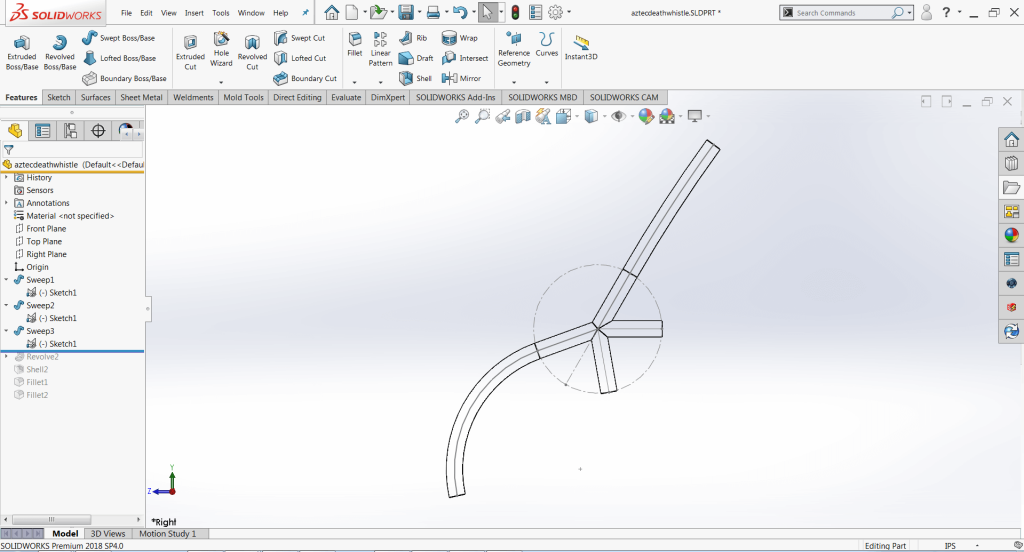


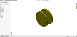
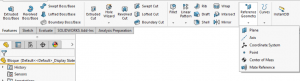


 Figure 1: Gas Cap Isometric View
 Figure 3: Sketch Ink Command Manager.
 Figure 5: Remaining Sketch Ink Commands
 Figure 6: Cloud drawn using Auto Shape.
 Figure 7: Update to Entities command.
 Figure 8: Updated Entities.
 Figure 9: Using Auto Sketch Entities.


 Animation, 3D Art and 3D Models")