


Hawk Ridge Systems Blog Nicole Drake
After receiving her undergraduate degree from the University of California - San Diego, Nicole entered the engineering community with a focus on marketing, public relations, and sales. Her career prior to joining Hawk Ridge Systems focused on helping engineering services start-ups provide … More » The Top 10 New Features in SOLIDWORKS 2019November 19th, 2018 by Nicole Drake
SOLIDWORKS adds hundreds of new features every single release – and SOLIDWORKS 2019 is no exception. With great improvements in assembly performance, new workflows, and new surface texture features, SOLIDWORKS continues to innovate in 3D CAD. THE BEST OF SOLIDWORKS 2019 RELEASE1. NEW 3D TEXTURE TOOL
2. IMPROVED EDITING WITH LARGE ASSEMBLY TOOLS
Aztec Death Whistle Designed with Hawk Ridge Systems SolutionsOctober 31st, 2018 by Nicole Drake
It’s Halloween here at Hawk Ridge Systems, and we take the holiday dead serious. To spook my fellow co-workers, I decided to undertake a project I’ve been mulling over since I read an article about one last Halloween; the Aztec Death Whistle.
The Aztec Death Whistle, rather than being a cursed object, is really just a cleverly shaped whistle that mimics the sound of the agonizing screams and wails of captives being tortured. Neat! Since I didn’t have the genuine article to study (might need to buy one when I go down to Mexico in April!) I had to use the interweb. I was able to gather these cutaway views from various articles and google searches, with no real guarantee any of these are based on authentic Aztec Death Whistles and not themselves just approximate recreations. With this understanding, I knew I might have to take a few attempts to perfect the air pathways and resonating chamber to get the terrifying effect I’m after.
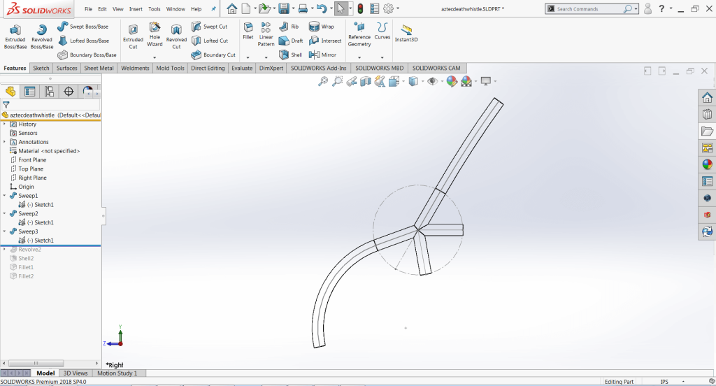
Next, I broke open SOLIDWORKS and set about making my prototype of the whistle air chambers. Since I didn’t have the time to make a skull and everything from scratch, I was already planning to use an STL or mesh body and carve away the internal chambers; so instead of creating a negative of the internal passageways, I went with a positive I could use as a subtraction tool later. This involved making a very simple right-hand sketch of the path of the air passages first and then using the new Circular Profile options in the Sweep tool to get the areas where air would flow in and out. Doing it this way also means I can come back and adjust the internal cavity shapes later to my heart’s content, and either update the whistle with the new internal geometry or create an entirely different whistle using the same internal geometry and a different body/exterior. This is important at this stage because I’m not 100% positive the geometry I have will even work, so I need to be able to quickly revise and update it later. The resonating chamber was added next, as a simple half circle Revolves and merge feature.
With the body of my whistles’ internal cavities finished, next, I turned my attention to the final whistle itself. As I mentioned earlier, I didn’t have the time to make a good quality skull model using surfacing tools and my (lack of) artistic ability meant I was going to do what every good engineer does; look for an off the shelf solution. Why reinvent the skull when others have for you? I went to Thingiverse and got this fantastic skull STL that was already watertight as a cohesive single body. This is a kind of important factor since I didn’t want to spend any time at all really cleaning up this skull model before adding my own geometry and printing a prototype. I want to try my whistle dang it! Credit to YahooJapan for the STL.
“But wait!” you say, knowing SOLIDWORKS doesn’t always play nice with STL files, “How are you going to use that geometry?” Convert to Mesh Body baby.
Introduced in SOLIDWORKS 2018, Convert to Mesh Body has been one of my favorite hack and slash tools, making quick work of otherwise scary jobs. In this case, the thought of recreating this skull or making one from scratch or bringing in this STL and trying to convert facets into surfaces and knitting into a cohesive face/body is downright terrifying. So instead, I opened the Skull STL, inserted my whistle body as a part, and converted both to mesh bodies. This allowed me to play with both sets of geometry using SOLIDWORKS tools and combine them together. I positioned the internal whistle cavity body where I wanted inside the Skull STL, and then I used the Combine tool to subtract away the areas of the Skull where air would flow. To cap it off, I created a mouthpiece using native SOLIDWORKS geometry, converted it to a Mesh Body, and then also Combined it with the rest of the shape. Now I had a full Aztec Death Whistle Prototype, and I could move on to 3D printing one for testing and refinement.
Finally, I exported this finished Mesh Body as an STL again, so I could load it into my slicer software for 3D printing. As of this writing, I am waiting for my prototype to leave the printer! Stay tuned for a future article where we simulate, test, and refine this Whistle using SOLIDWORKS Flow Simulation tools.
Create your own spooky designs with SOLIDWORKS by starting your FREE Trial Today! Building a Better Off-Roading Experience with SOLIDWORKSOctober 26th, 2018 by Nicole Drake
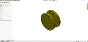
Learn how Alien Machine Worx went from idea to product in no time with SOLIDWORKSDifferential covers play an important role in keeping your wheels turning and protecting gears from dirt and moisture. For Alien Machine Worx, creating differential covers with maximum strength and ease of use provides off-roading customers with big benefits. Watch the video to learn how this family-owned business uses the SOLIDWORKS integrated, design-to-manufacturing solution to:
SOLIDWORKS 3D CAD design solutions provide engineers, designers, and manufacturers with advanced tools to create, validate, communicate, and manage product designs. With over 4.7 million users, it is the fasted growing 3D design software on the planet. It is the preferred 3D design and manufacturing choice for global enterprises, small & medium businesses, and entrepreneurs. If you can think it, you can design it! Put your designs to the test and sign up for our free trial to see what game-changing trends you can start with your innovative designs today. Hawk Ridge System Expands Portfolio with Predator SoftwareOctober 15th, 2018 by Nicole Drake
Hawk Ridge Systems, the leading provider of 3D Design and manufacturing solutions announces a partnership with Predator Software to provide customers with a complete shop floor CNC solution. This partnership will directly influence all sectors of the manufacturing shop floor to both measures and increase the productivity of your CNC machines and manufacturing tasks. Hawk Ridge Systems will now provide software, hardware, installation, and support services to assist in controlling and automate the shop floor. With the acquisition of Cimtronics Midwest in May of 2018, Hawk Ridge Systems is now the largest distributor of Predator Shop Floor Manufacturing Software in North America. GEARED FOR MANUFACTURING™Maximize the productivity and quality of your people, machines, robots, CNCs, PLCs and processes with Predator Software Systems. Software Products
Jawstec Chooses Hawk Ridge Systems and HP Jet Fusion 3D PrintersOctober 12th, 2018 by Nicole Drake
Idaho Bureau Chooses HP Jet Fusion 4200 3D Printer to Enhance its OfferingsJawstec started with a simple goal in mind; to create a simple process where you can get production ready parts for a fraction of the cost. They offer a unique depth of custom manufacturing and 3D printing services to a variety of industries including Automotive, Consumer Products, and Aerospace for both small or large businesses. With the growing demand for Unmanned Aerial Vehicles (UAV) in recent years, Jawstec took it upon themselves to design an optimized drone. Unlike radio-controlled planes and helicopters, the product development varies in time and costs. Jawstec designed an enhanced drone with 3D Printing to make its parts stronger and lighter. The Jawstec team took it to open themselves to create a design that was more durable for the vast environment the drone would take flight in. They utilized HP Multi Jet Fusion 4200 3D Printer and Nylon PA 12 plastic materials for the parts. Their total design time took 18 hours with SOLIDWORKS and the total print time was 4 hours. The engineers’ focus was to design a drone that was stronger and lighter, and with the HP 4200 3D Printer it weighed 200 grams lighter than the original drone design and increased its total flight time to 28 minutes. Jawstec’s design team was able to print up to 10x faster and reduced their product development costs by half. This wouldn’t have been possible without HP robust and accurate multi-jet fusion technology. SOLIDWORKS: Basics of Reference GeometrySeptember 28th, 2018 by Nicole Drake
Utilizing SOLIDWORKS Reference Geometry for Complex DesignsFor basic SOLIDWORKS models, users can often complete designs by leveraging only the default planes and available model geometry. However, as the complexity of designs increases, it often becomes necessary to create and utilize reference geometry to produce models with appropriate design intent. Reference geometry includes planes, axes, coordinate systems, reference points, the center of mass, and mate preferences. In this article, we’ll cover the basics of creating planes, axes, and coordinate systems to help you throughout your design process. Fly Reel DesignIn this example, a fly reel is being designed, and so far everything has been smooth sailing. At this point, we want to create a rectangular cut on one of the larger cylindrical surfaces of the fly reel, but there is no flat surface to create a sketch. While offset options in the Extruded Cut command could be used to accomplish this, creating a plane tangent to the surface will be more robust, and will result in better design intent should the design be resized in the future.
Features TabAll types of reference geometry are considered features and can be found in the Features tab. To begin creating a plane, access the Features tab of the CommandManager, select Reference Geometry, and then click Plane. SOLIDWORKS: Tips for Creating Organized Title BlocksMarch 29th, 2018 by Terence Woo
There’s a lot that goes into creating SOLIDWORKS drawing templates – sheet formats, linked custom properties, document properties, and more. With all of this, one topic that often gets overlooked is how to keep your title blocks neat and organized. Here are some tips to help. Read the rest of SOLIDWORKS: Tips for Creating Organized Title Blocks SOLIDWORKS: Continuity and Curvature Part IIMarch 24th, 2018 by Rony Godoy
In Part I of this series, we looked at how the smoothness of curves can be analyzed and controlled. Now we’ll be taking a look at some additional analyses tools to further evaluate our surfaces as well as ways to improve our curvature continuous connections.
The zebra stripes tool (view>display>zebra stripes) allows us to see small changes on a surface that may be hard to see with a standard display. This tool mimics the reflection of long stripes of light on a very shiny surface. With zebra stripes, we can verify that two adjacent faces are in contact, are tangent, or have continuous curvature. As can be seen in the image below, the zebra stripes for contact do not have the same direction or size. The zebra stripes for tangent have the same direction, but change sizes where the tangency occurs – there are two points of tangency. And the curvature continuous stripes share the same direction and the same size throughout the entire surface. Read the rest of SOLIDWORKS: Continuity and Curvature Part II SOLIDWORKS Flow Simulation: Solving the Bucket ChallengeMarch 20th, 2018 by Dayne McGuire-Lavallee Dayne
For all the SOLIDWORKS designers and engineering enthusiast out there, I’m sure you have seen something like this come across your social feeds at one time or another cause I know I have. The question is which bucket will fill up first if water is poured continuously into the first bucket. I have spent some time in the comments sections of these puzzles and been baffled by some people’s logic and responses. Most of the time there is a trick like a closed drain or hole in a bucket but some people were so confident in their wrong answer that I started to doubt my own intuition. So I decided to make a puzzle of my own and verify my intuition with SOLIDWORKS Flow Simulation. The modeling was very easy with some revolves and thin extrudes and below is what I came up with. If you were at any of our rollout events this should look familiar.
I modified the problem statement a bit with some assumptions so everyone can understand the intent of the problem and to potentially combat any over-analyzed responses. Water will be poured into bucket 1 at a slow enough flow rate that it will drain before it begins to fill. The system is open at the ends so there will be no buildup of air. Which bucket will fill first? I had to modify the problem statement for a couple of reasons because if I dumped the ocean into the problem bucket 1 would fill first so we are assuming the flow rate is ideal for the buckets drain faster than they fill. This cross-sectional view shows lids on the buckets and those are only there to help define the boundaries in the flow simulation but are considered pipe openings so there will be no air buildup. I challenge you to examine this puzzle and determine which bucket will fill first. Before I give you the answer I am going to talk about the free surface flow simulation that I used to solve this puzzle. Free surface lets you simulate flows with a freely moving interface between two immiscible fluids. It’s like water flowing in an open channel or a half full pipe. It uses the volume of fluid method for tracking and locating the free surface interface of gas-liquid or liquid-liquid pairs. Any phase change, rotation, porous media, or fans are not allowed. For more information and an additional example of free surface flow inside of SOLIDWORKS flow simulation check out this BLOG.
So now I present the solution brought to you by SOLIDWORKS Flow Simulation. I am happy to say that the simulation went just as I planned, giving me a lot of confidence in my own intuition and the capabilities of SOLIDWORKS flow simulation. For more information, check out our website to get a SOLIDWORKS Flow Simulation Quote or contact us at Hawk Ridge Systems today. Thanks for reading! Dual Graphics Cards Causing Issues with SOLIDWORKS Graphical DisplayMarch 7th, 2018 by Nikki Stakic
Note: This blog is intended for users who have a combination of either onboard Intel HD Graphics + NVIDIA graphics cards or onboard Intel HD Graphics + AMD graphics cards on their computers. Let’s start this blog post with a little story. I was so excited when I found out I was going to be getting a new laptop that had better performance specifications. Mainly what mattered is that I was going to get better performance for my SOLIDWORKS designs. After security and antivirus program installations were done, it was time to install SOLIDWORKS! The software managed to install itself with a smooth sail and my next step was to download my SOLIDWORKS settings from my previous computer using the Copy Settings Wizard that comes with any standard installation of SOLIDWORKS. With my customizations set in place, I was ready to play! So, my final step was to open my model and keep adding more details to it but I encountered a graphical issue I did not expect. Every time I would try to rotate or move the model, my screen would get really glitchy and the graphics didn’t want to update and I became frustrated very fast. My first thought was that I did not have the latest driver for my NVIDIA graphics card. In order to do this, there are two options how a user can check the latest driver available for their graphics card: Read the rest of Dual Graphics Cards Causing Issues with SOLIDWORKS Graphical Display |
|
|
|||||
|
|
|||||
|
|||||


 Animation, 3D Art and 3D Models")