Bit-Slice Design: Controllers and ALUs
by Donnamaie E. White
Copyright © 1996, 2001, 2002 Donnamaie E. White
- Pre-Introduction
- Selection of the Implementation
- Microprogramming
- Advantages of LSI
- The 2900 Family
- Language Interrelationships
- Controller Design
- Constructing the CCU
- Sequential Execution
- Multiple Sequences
- Start Addresses
- Mapping PROM
- Unconditional Branch
- Conditional Branch
- Timing Considerations
- Pipelining
- Improved Architecture
3. Adding Programming
Support to the Controller
- Expanded Testing
- Subroutines
- Nested Subroutines
- Stack Size
- Loops
- Am29811
- Am2909/11
- CASE Statement (Am29803A)
- Microprogram Memory
- Status Polling
- Interrupt Servicing
- Implementation - Interrupt Request Signals
- Vector Mapping PROM
- Next Address Control
- Am2910
- Am2910 Instructions
- Control Lines
- Interrupt Handling
- Am2914
- Interconnection of the Am2914
6. The ALU and Basic Arithmetic
- Further Enhancements
- Instruction Fields
- Instruction Set Extensions
- Sample Operations
- Arithmetic -- General
- Multiplication with the Am2901
- Am2903 Multiply
IntroductionLast Edit Ocober 10, 1996; July 9, 2001 Controller DesignA computer control unit (CCU) will be used for illustration throughout the text; the design approach, however is applicable to any controller. A Simple ComputerThe simplex computer of Figure 1-1 is further reduced as shown in Figure 1-6, which shows the
Figure 1-6 CPU and control block diagram
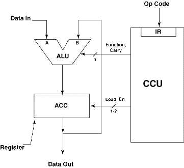
The MAR is the output to the address bus for peripheral and memory addressing. The CCU controls all devices shown and outputs to external devices via the control bus. The ALU receives and outputs data via the data bus. Addresses may be loaded into the PC via the data bus. This is a very elementary system. This system is further reduced in Figure 1-7, where the CCU is shown to control the ALU and the ACC (accumulator, a register) with its other control functions ignored for now. Here the data may be input only via port A of the ALU; port B is loaded via the ACC register; the data is output only from the ACC. The CCU receives an instruction in the form of an op code somehow - ignore how at the moment. Given the op code as input, the CCU must proceed to generate
Figure 1-7 Simple computer system (simple computer, SIMCOM)
Figure 1-8 Control required from the CCU
A simple ALU could have three control lines and perform addition, subtraction and the logical OR, AND, EXOR, etc. Functions. The carry-in bit allows the three arithmetic functions A + B, A - B, and B - A to be varied to A + B + 1, A - B - 1 and B - A - 1. This simple ALU would support the machine level and assembly instructions: ADD, SUB, OR, AND and EXOR, as shown in Figure 1-9. Figure 1-9 ALU Functions
|