


Utilizing SOLIDWORKS Reference Geometry for Complex Designs
For basic SOLIDWORKS models, users can often complete designs by leveraging only the default planes and available model geometry. However, as the complexity of designs increases, it often becomes necessary to create and utilize reference geometry to produce models with appropriate design intent. Reference geometry includes planes, axes, coordinate systems, reference points, the center of mass, and mate preferences. In this article, we’ll cover the basics of creating planes, axes, and coordinate systems to help you throughout your design process.
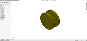
Fly Reel Design
In this example, a fly reel is being designed, and so far everything has been smooth sailing.
At this point, we want to create a rectangular cut on one of the larger cylindrical surfaces of the fly reel, but there is no flat surface to create a sketch. While offset options in the Extruded Cut command could be used to accomplish this, creating a plane tangent to the surface will be more robust, and will result in better design intent should the design be resized in the future.
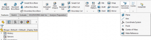
Features Tab
All types of reference geometry are considered features and can be found in the Features tab. To begin creating a plane, access the Features tab of the CommandManager, select Reference Geometry, and then click Plane.


 Animation, 3D Art and 3D Models")