Bit-Slice Design: Controllers and ALUs
by Donnamaie E. White
Copyright © 1996, 2001, 2002 Donnamaie E. White
- Pre-Introduction
- Selection of the Implementation
- Microprogramming
- Advantages of LSI
- The 2900 Family
- Language Interrelationships
- Controller Design
- Constructing the CCU
- Sequential Execution
- Multiple Sequences
- Start Addresses
- Mapping PROM
- Unconditional Branch
- Conditional Branch
- Timing Considerations
- Pipelining
- Improved Architecture
3. Adding Programming
Support to the Controller
- Expanded Testing
- Subroutines
- Nested Subroutines
- Stack Size
- Loops
- Am29811
- Am2909/11
- CASE Statement (Am29803A)
- Microprogram Memory
- Status Polling
- Interrupt Servicing
- Implementation - Interrupt Request Signals
- Vector Mapping PROM
- Next Address Control
- Am2910
- Am2910 Instructions
- Control Lines
- Interrupt Handling
- Am2914
- Interconnection of the Am2914
6. The ALU and Basic Arithmetic
- Further Enhancements
- Instruction Fields
- Instruction Set Extensions
- Sample Operations
- Arithmetic -- General
- Multiplication with the Am2901
- Am2903 Multiply
Refining the CCULast Edit December 9, 1996; May 1, 1999; July 10, 2001 Interrupt HandlingIn a computer system, the minimal storage required for the system to be able to resume operations after handling an interrupt would provide the ability to store the PC register and the PSW, which includes the ACC register and the status bits. More complicated systems require additional storage, such as the storage of the current stack pointer, scratchpad registers, and all other machine registers. Nested interrupts are handled in software by stack operations and subroutine call procedures. Enable/disable capability and clear interrupt mechanisms are essential. Clear interrupts can be clear one, clear several, or clear all current interrupts in a system. Refer to Figure 4-26 for the flow of interrupt handling via software; it is seen to be markedly identical to subroutine handling. Figure 4-26 Interrupt Handling program flow (recoverable status)
Clearing InterruptsTo be able to clear the current interrupt using the interrupt hardware developed earlier, the vector map index generated by the priority encoder must be brought out to flip-flops for storage. A control bit from the pipeline will cause the actual storage operation. The flip-flops feed a decoder, which is enabled under pipeline control. When the decoder output is enabled, it drives the clear lines into the latches and the interrupt registers. Interrupt EnableOccasionally it is desirable to block one or more interrupts during a program, such as
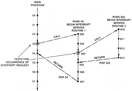
Bit masking can be added to the control being constructed by adding a loadable mask register which will block all masked bits from being input to the priority encoder or from triggering the interrupt request line. Nested InterruptsNested interrupts behave as nested subroutine calls, as shown in the flow diagram of Figure 4-27. When multi-level interrupts can exist, a higher priority interrupt must be able to interrupt a lower-level one. Figure 4-27 Nested interrupt flow (recoverable status). Recovery of addresses same as nested subroutines.
In a microprogram-controlled interrupt system, the presence of an interrupt is tested for by a conditional test statement such as CJP or CJS. The test should be made at a quiescent point in the microroutine, usually where the stack activity is low and the counter/register is not in use. No interrupts should be tested for within a loop or a subroutine nest. Care must be exercised to prevent the stack from overflowing. Status FenceTo implement a nested interrupt capability, a status fence is required. Because there is a particular device in mind, this is shown in Figure 4-28 to consist of
Figure 4-28 Clear control, status fence and bit marking for interrupt controller
The comparator will generate a signal when the incoming interrupt is equal to or greater than the current status. This signal will be NANDed with the interrupt signals from the unmasked interrupts to generate an active low signal to be input to the CC' pin of the Am2910 or to a conditional MUX input pin. Also, the comparator output enables tristate buffers that control the output of the actual interrupt vector index to the vector map. Other EmbellishmentsTo recover from an interrupt or to unwind an interrupt nest, the status and mask registers must be readable (so that they can be saved) as well as loadable (so that they can be restored). The control should be able to use the mask register or mask register input bus to selectively clear some or all interrupts to expand interrupt clear capability. |