Bit-Slice Design: Controllers and ALUs
by Donnamaie E. White
Copyright © 1996, 2001, 2002 Donnamaie E. White
- Pre-Introduction
- Selection of the Implementation
- Microprogramming
- Advantages of LSI
- The 2900 Family
- Language Interrelationships
- Controller Design
- Constructing the CCU
- Sequential Execution
- Multiple Sequences
- Start Addresses
- Mapping PROM
- Unconditional Branch
- Conditional Branch
- Timing Considerations
- Pipelining
- Improved Architecture
3. Adding Programming
Support to the Controller
- Expanded Testing
- Subroutines
- Nested Subroutines
- Stack Size
- Loops
- Am29811
- Am2909/11
- CASE Statement (Am29803A)
- Microprogram Memory
- Status Polling
- Interrupt Servicing
- Implementation - Interrupt Request Signals
- Vector Mapping PROM
- Next Address Control
- Am2910
- Am2910 Instructions
- Control Lines
- Interrupt Handling
- Am2914
- Interconnection of the Am2914
6. The ALU and Basic Arithmetic
- Further Enhancements
- Instruction Fields
- Instruction Set Extensions
- Sample Operations
- Arithmetic -- General
- Multiplication with the Am2901
- Am2903 Multiply
Adding Programming Support to the ControllerLast Edit November 1, 1996; May 1, 1999 ; July 9, 2001 The CCU developed in Chapter 2 is a high-speed unit capable of making decisions and branching around in the PROM control memory. Any problem may be programmed if GOTO and IF equivalent programming structures exist. The limitations are:
Expanded TestingThe first change is to expand the number of testable conditions. This is easily done by expanding the branch condition selection MUX which inputs to the next address MUX selection logic. Next, allow testing to be for IF Ci or for IF NOT Ci. This is done by adding a polarity select bit to the microword and a polarity logic block between the condition MUX and the next-address logic block. This improved CCU is shown in Figure 3-1. Figure 3-1 Expected Conditional Testing
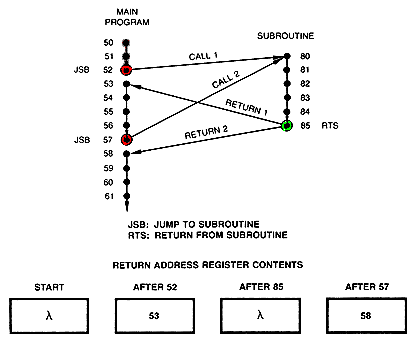
SubroutinesUp to this point, when a branch is executed, the only way to return from the branched-to routine is to execute another branch, and the programmer has to know the exact address. This is fine as long as the branched-to code is accessed by only one source routine and is required to return to only one source or calling location. When two or more microroutines need to branch to the same piece of code, and it is necessary to return from executing that code to the specific routine that called it, GOTO and IF structures are inadequate. It is now desireable to provide a means of storing the address of the calling statement and a means of accessing this storage for the return address. This ability in a higher-level programming language exists as SUBROUTINES or PROCEDURES. A subroutine can be called from anywhere in a program, and the return to the next statement following the calling statement is made either upon completion of the execution of the subroutine --- an unconditional return -- or upon the successful test of a condition --- a conditional return. Subroutine should be more than one or two statements long to avoid choppy code. (Debug and maintenance features must be stressed in any large microprogram, just as they are in any other programming language.) A flow of subroutine calling program is shown in Figure 3-2. When the statement at address 52 calls the subroutine, address 53 is pushed into the return address store. Hen the return statement at address 85 is excuted, the return address is "popped' from the store which provides the addres of the next microinstruction. Figure 3-2 Subroutine Flow (JSB, Jump to subroutine; RTS, Return from subroutine; lambda, garbage)
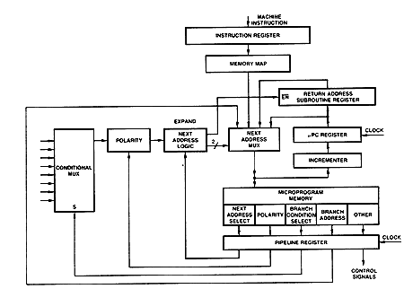
The hardware required to enable the CCU to do this is shown in Figure 3-3. The next-address select logic is expanded to add a load enable to the return address register. When a CALL instruction is executed, a branch to the subroutine is handled as any other branch with the addition that the contents of the µPC are copied into the return address register. The incrementer contains the address of the second step of the subroutine. Figure 3-3 Expected Conditional Testing
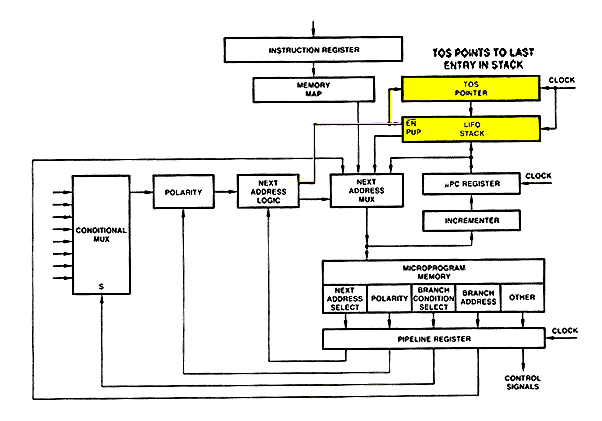
To return, the RETURN statement will cause the next-address MUX to select the return address register outputs as the source of the next PROM address, with execution proceeding as if an unconditional branch had occurred. Nested SubroutinesNested subroutines are flow diagrammed in Figure 3-4. Nested subroutines require more than one return address location and a means of keeping track of the order of the calls. This is accomplished by using a LIFO (last in, first out) stack, pushing an address onto the stack when a CALL is executed and popping an address off, when a RETURN is executed. A stack pointer is used to point to the last entry, which is the top of the stack (TOS). The same rules that exist for any programming language apply for nested subroutines. When subroutines are nested, the call returns are treated as parenthesis in an algebraic equation -- that is, if subroutines 3 calls subroutine 4, then subroutine 4 returns to a point in subroutine 3. Subroutine 4 cannot jump out of the subroutine nest in one step. Each return address must be popped from the stack in the order in which it was pushed onto the stack. The TOS pointer can be incremented (for a PUSH) or decremented (for a POP) only by one. Figure 3-4 Nested Subroutine Flow
The hardware to allow this is shown in Figure 3-5. A LIFO stack replaces the return address register, and a TOS pointer, a simple counter, has been added. The next-address logic is expanded to provide load enable and PUSH/POP controls to the stack and increment/decrement (INC/DEC) controls to the pointer. Figure 3-5 Adding the FILO Stack and TOS Pointer
When a subroutine is called, the branch address passes as before. The TOS pointer is incremented, and the µPC is moved into the LIFO stack to the position indexed by the TOS pointer. When a return statement is executed, the contents of the stack location referenced by the TOS p[ointer are gated by the next-address select MUX into the PROM memory. On the next cycle the TOS pointer is decremented. |


